
This section is crucial as it tells the firmware exactly how your physical components are wired to the microcontroller.
Hardware Mapping
This stage of the wizard is where you define the “wiring map” for your project. This data is stored in the board’s EEPROM, allowing the OpenSR plugin to know exactly which pin corresponds to which button, LED, or axis.
Note: Pin numbers range from 0 to 200. If a specific input is not connected to your hardware, leave the pin field empty.
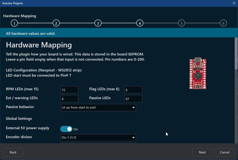
LED Configuration
Configure your addressable NeoPixel/WS2812 LED strips:
- LED Start Pin: The wizard indicates the pin number to which the LED data line should be connected, depending on the selected board.
- LED Counts: Enter the number of LEDs for each category:
- RPM LEDs: (Up to 15)
- Flag/Warning LEDs: (Up to 6)
- Ext/Warning LEDs: (Up to 24)
- Passive LEDs: Used for static lighting on your device. Enter the number of passive LEDs, ensuring that the total number of LEDs across all categories does not exceed 112.
- Passive Behavior: Select how your passive LEDs should behave (e.g., “Lit up from start to end”).
Global Settings
Adjust the core electrical and communication parameters:
- External 5V Power Supply: Toggle this ON if you are using an external power source for your LED strips. This is highly recommended for large LED arrays to avoid overtaxing the Arduino’s onboard regulator.
- Encoder Divisor: Choose the pulse divisor for your rotary encoders (1:1, 1:2, or 1:4).
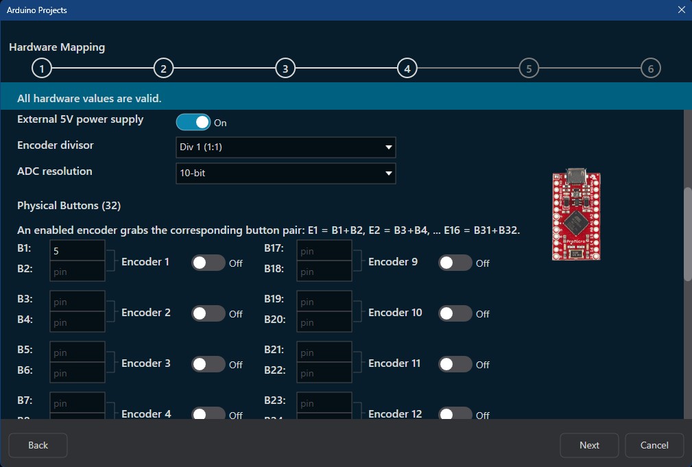
- ADC Resolution: This defines the bit-depth of your analog inputs. The wizard will automatically select the optimal resolution (10-bit or 12-bit) based on the board model you chose in the previous step.
Physical Buttons & Encoders
Map your buttons and rotary encoders to specific pins.
- Button Logic: Enter the pin number for each of the 32 available buttons.
- Encoder Pairing: The system uses a “Pairing” logic for encoders. When you enable an encoder (e.g., Encoder 1), it automatically “grabs” the two buttons associated with that position (e.g., B1 and B2). This allows you to use the same pins for either a button or an encoder depending on your build.
(Insert Screenshot: Buttons_and_Encoders_Section.jpg)
Analog Axes & Rotary Switches
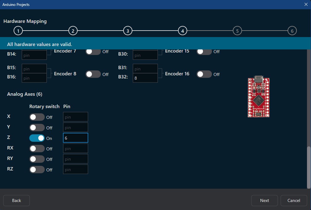
Define your axes (X, Y, Z, RX, RY, RZ) and their physical connection:
- Raw Axis: If the “Rotary switch” toggle is OFF, the firmware treats the input as a standard raw analog axis.
- Rotary Switch: If you toggle Rotary switch ON, the firmware will take over the processing. Instead of sending a raw analog value, it will detect the physical detents and send a discrete position number from 0 to 11. This is ideal for 12-position rotary switches.
Next Step: Click Next to proceed to setup the LED colors configuration and testing phase.